What is PS and TMS in Overcurrent and Earthfault Relay ?
Plug Setting (PS) and Time Multiplier Setting (TMS) are the Settings that are to be entered in the Numerical Overcurrent and Earth Fault Relay. When the current flowing through the Current Coil of the Relay exceeds the Plug Setting, the Relay Operates in the time that is as per the TMS set in the Relay.
The Concept of Plug Setting and Time Multiplier Setting are derived from Electromechanical Relays, but their implementation is quite different in Numerical Relays.
What is Plug Setting (PS)?
Answer:
Plug Setting is the Current Setting of the Relay.
It is given by the Percentage of the Relay Nominal Current (In), which when flows through the Relay, the Relay Operates.
Where the Relay Nominal Current (In) is kept the same as the CT Secondary Current which is usually 1A or 5A.
PS= (Ipu/In) x 100
For Line/Feeder Ipu is generally kept as 120% of Maximum Current flowing through the Feeder/Line.
The term ‘Plug Setting’ came from the Electromagnetic Relay, where the position of the Plug (a small Short Link) decides the Pickup Current of the Relay.
The Resistance is connected in Series with the Relay Operating Coil and the Plug connects the relay Operating Coil and the Resistance. When a Plug is inserted, Resistance Values are added .
Higher the number of Plug Position, higher is the resistance Value and so higher is the value of current required to energize the Operating Coil.
Before understanding Time Multiplier Setting (TMS) we need to understand the concept of Plug Setting Multiplier (PSM), Relay Curve and Relay Operating Time (ROT).
What is Plug Setting Multiplier (PSM)?
Answer:
PSM is the Ratio of Fault Current fed to the Relay in Secondary to the Plug Setting.
It indicates the Severity of the Fault. PSM setting is not entered in the Relay, but used to calculate the TMS value.
PSM= If sec/ Ipu
What is Relay Operating Time (ROT)?
Answer:
It is the desired Operating Time of the Relay.
In the Electromagnetic Relay, changing the position of the TMS setting changed the distance between the contact of the rotating disk and the coil. If it is more, the Relay will take more time to Operate.
In the Numerical Relays it depends upon the TMS, PSM and Relay Operating Curve.
Let’s say we are using Standard or the Normal Inverse Curve.
Relay Operating time is given by, ROT = TMS x (3/Log PSM)
From the above formula, the ROT can be made faster or slower by changing the TMS or the PSM or the Relay Operating curve.
PSM cannot be changed as we cannot control the Fault Current and the Plug Setting is already fixed by us.
So, the only thing that can change the ROT is the TMS and Relay Operating Curve.
So for a desired ROT, TMS is given by the formula:
TMS = ROT / (3/Log PSM)
What is Time Multiplier Setting (TMS)?
Answer:
It is the Time Setting of the Relay which controls the Operating Time of the Relay (ROT). It decides in what time the Relay should Operate.
TMS = (3/Log PSM)/ ROT.
Explain PS & TMS with an Example?
Answer:
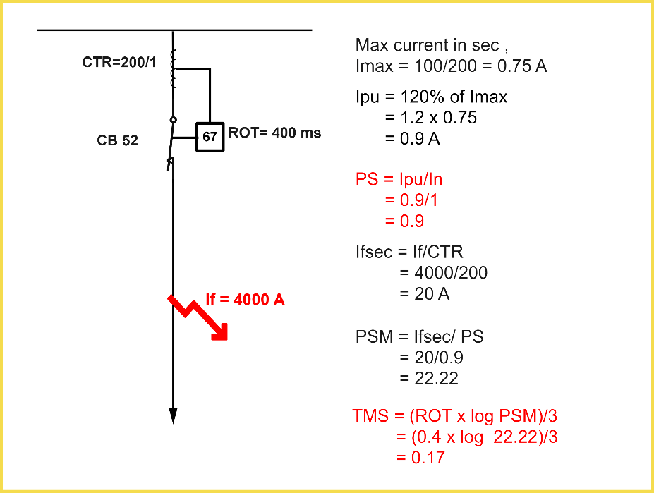
Lets say, Maximum Current flowing through the Transmission Line , for the last Six Months or Full Load Current in case of Transformer, Imax= 150 A
Lets say CTR is 200/1.
Imax in Secondary= Imax/CTR = 100/200 = 0.75A
Let’s say Relay Nominal Current, In= 1A
Plug Setting or the Pickup Current,
Ipu= (120% of Imax sec)/ In = 1.2 x 0.75 = 0.9 A or 90%
PSM= If sec/ Ipu
Let’s say Fault Current, If sec = If/CTR = 4000/200 = 20 A
PSM = 20 / 0.9 = 22.22
Let’s say we are using a IDMT Normal Inverse 3 (10C3 ) Curve.
TMS = ROT / (3/Log PSM)
Let’s say we want the Relay to Operate in 400 ms.
TMS = 0.4/ (3 / Log 22.22) = 0.17 seconds